


 My Account


Aftermarket Upgrades: Parts selection and installation
When released to the public back in the day, the Second Generation Trans Ams (’70-’81) were exceptional from a ride, drive, and handling perspective versus the competition. While still a subframe-architecture vehicle, the generation’s suspension improved over the model years, especially with Pontiac’s new Radial Tuned Suspension, which took advantage of radial-tire technology.
Fast-forward to 2013. A great number of still-in-existence Trans Ams and Formula Firebirds are restored and modified to perform beyond what Pontiac designed. The aftermarket for suspension technology is rapidly expanding, and after manufacturers initially focused on the First-Generation F-body platform, the Second-Generation is now coming on strong.
Pro-Touring F-Body (PTFB) is at the forefront of Second-Gen suspension expertise and its line of specific parts is branded as Gen II Racing. Owner Dave Masello is an enthusiast. “My business is Second-Generation specific, and grew out of my desire to make F-bodies handle and perform better on the street and track,” he says.
PTFB offers a wide range of upgrades, from full suspension kits for stock restorations all the way to track setups that will allow your Second-Gen to compete in various competitive driving classes. After speaking with the owner of a ’79 Trans Am who desired better handling replete with a modern wheel/tire combination, HPP and Whiteside Customs teamed up with PTFB to put together a suspension package that would increase handling beyond the WS6 performance offered by Pontiac and serve as a foundation for additional modifications.
Now let’s tell you about our test car. It’s a ’79 Trans Am, now in possession of its second owner, Randy Jamison. The T/A sports an Olds 403 engine, automatic trans, and air conditioning, and was cosmetically restored in 2000. The non-WS6 Bird has just over 100,000 miles on the odometer and is mostly original.
Since owning it, Randy has partially rebuilt the front end and replaced the original steering box with a WS6-spec unit. He’s also replaced the shocks and end-link bushings. We think it’s a good vehicle for testing because it is representative of many Trans Ams in the enthusiast community today—that is, a nearly unmodified vehicle that has wear, but is functional to drive.
Randy says his T/A’s handling is soft, vague, and not performance-oriented. Let’s see how PTFB changes his impressions.
Whiteside Customs in McKinney, Texas, performed all of the work. It is known as the go-to place for late-model GTO and G8 suspension and performance modifications.
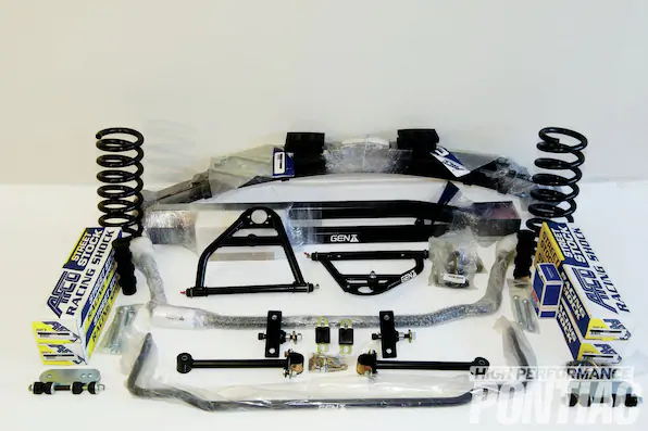
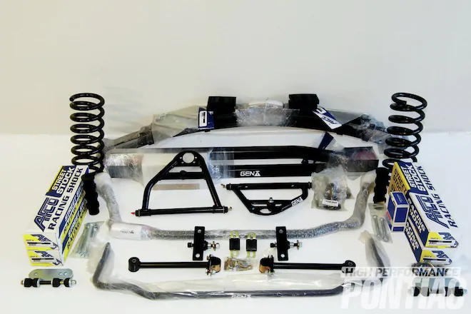
1. Pro Touring F Body’s Gen II 1LE Kit (PN 2CS 416/$779) Includes New Front Springs, Non Adjustable Shock Absorbers, Leaf Springs, And A Leaf Spring Installation Kit. The Company Offers Many Optional, Extra Cost Components Too, Such As Single Or Double Adjustable Shocks, Custom Rate Coil And Leaf Springs, And Suspension Drops.
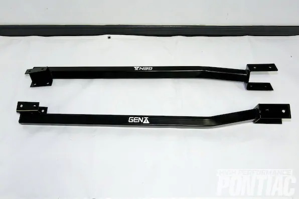
2. To Yield The Maximum Improvement Out Of The Kit, We Ordered Gen II’s Competition Upper Control Arms (PN 2CS 102, $339/set) Subframe Connectors (shown, PN2CF 821, $179), Front And Rear Sway Bars (OSC 500, $179; 2CS 511, $289) And 3 In 1, “key Lock,” Solid Body Bushings (PNOCF 801, $99).
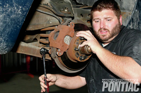
3. The First Step In Installing The Gen II Racing Suspension Is To Get The Firebird On A Lift And Remove The Two Front Wheels To Gain Access To The Control Arms, Springs, And Sway Bar. The Calipers Are Then Removed With A 3⁄8 Inch Allen Hex Head Socket, And The Two Long Bolts On Top And Bottom Are Extracted.
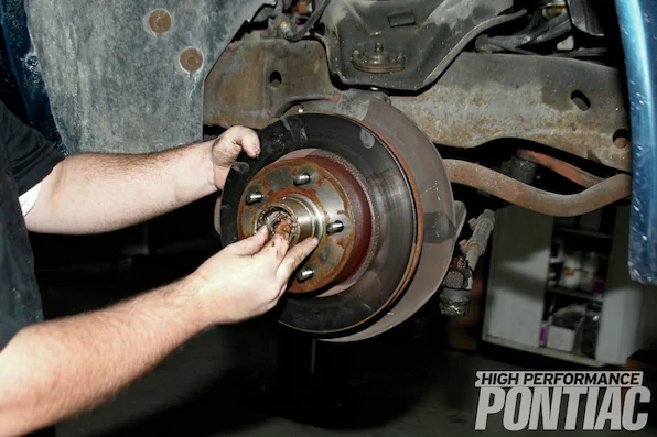
4. The caliper assembly (including disc pads) is carefully stored on the top of the control arm. The rotor is then removed after pulling the dust cap and the cotter pin that holds the spindle nut. The nut is removed with a 11⁄16-inch socket (or wrench) and stored. Note how Mike liberally applied penetrating oil, such as PB Blaster, to the sway bar and control arm to ease disassembly.
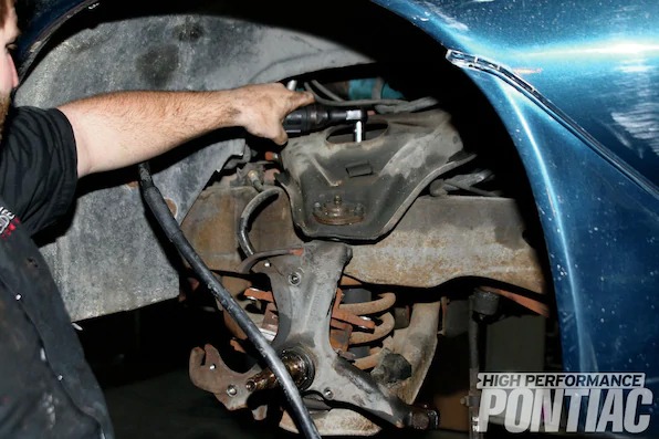
5. The three bolts that attach to the spindle to hold the dust shield in place are removed with a 1⁄2-inch socket. The front sway bar will be removed next by putting a 10mm wrench on the top of the sway-bar end-link bolt and a 10mm socket on the bottom. This style of end link is very popular. Mike struggled removing the nut and bolt due to the accumulated surface rust, but finally prevailed.
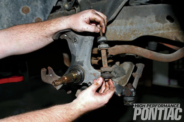
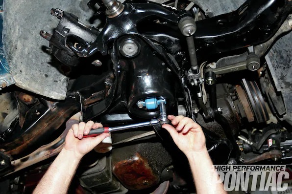
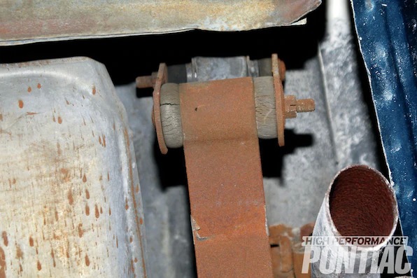
6. An illustration of the components comprising the end-link is shown to demonstrate how it attaches to the lower control arm and sway bar and the overall condition of the bushings. These bushings were replaced within the last five years, as the rubber was showing minor cracking where the bushings are compressed and slight deformation.
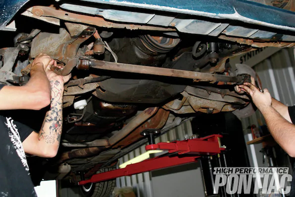
7. To extract the front sway bar, the driver’s side end link is removed and the two D-link sway bar casings and bushings that attach to the frame are loosened with a 1⁄2-inch socket. Once the bolts are almost out, a helper grabs one side and the bolts are removed and the bar is slowly lowered down. Although not a WS6 car, the front sway bar is 1.20 inches in diameter, as only the rear-bar size was raised from 0.625 to 0.750 inches for WS6 cars in ’79.
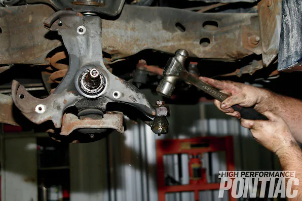
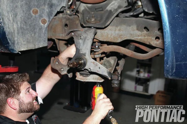
8. Disassembly continues with the removal of the outer-tie-rod ends. After pulling the cotter key, the 3⁄4-inch castle nut is loosened but not removed. A dead-blow sledgehammer is used to pound the top of the nut and underside of the tie rod until it unseats from the spindle. Although the tie-rods were both in good shape, replacement is necessary after this disassembly method. We sourced heavy-duty replacements from PTFB.
9. To remove the top nut holding the shock absorber on, we used a 9⁄16-inch socket. If the nut spins (which can sometimes be the case), snake some locking pliers onto the upper rod of the shock and remove the nut and washer.
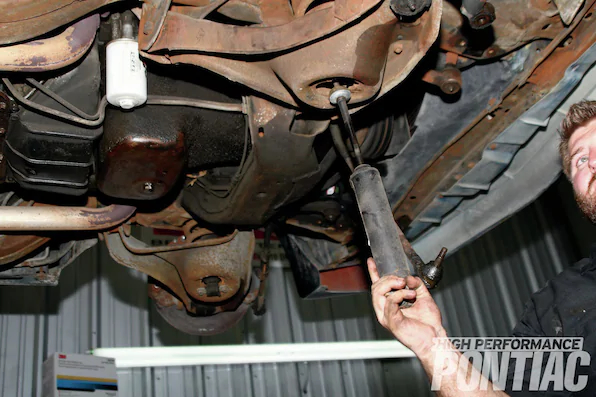
10. The two bolts that hold the shock in the lower mounts are easily removed with a 9⁄16-inch socket. Once the bolts are out, we pulled the shock out the bottom. In this case, the shocks were Monroe Sensa-Tracs, a common replacement shock that is nitrogen filled and calibrated for extra control and comfort. Although the shocks were not leaking, the fronts could be compressed by hand. That’s always a first indicator that replacement is needed.
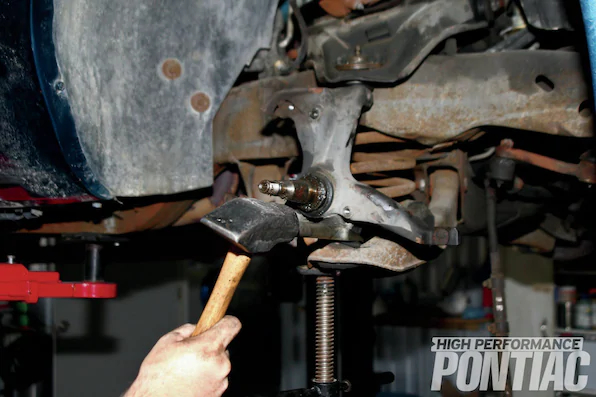
11. Mike loosens the castle nut on the lower ball joint with a 15⁄16-inch socket. Once it broke loose, a screw jack was placed under the lower control arm and the castle nut was removed. A ball-joint separator tool was used in conjunction with a sledgehammer to remove the ball joint.
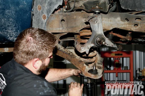
12. Mike slowly and carefully lowered the screw jack to release the pressure on the front coil spring. Unfortunately, after the pressure was completely off of the control arm, the spring was stuck.
Conclusion
In Part 2, we will install the rear leaf springs, body bushings, and rear sway bar, and then dive deep into the results of testing on a standardized slalom course and skidpad. Hang on as we push the T/A to the limits to determine how well the stock suspension and restoration-style wheel/tire combination perform, then up the ante and show you a comprehensive package that can go head to head with many late-model performance sports cars.
| Supplies Required | |
| Prybar | Cut-off wheel |
| Penetrating oil | Metric socket set |
| Metric wrenches | Torque wrench |
| Drill and drill bits | Pole jack |
| Floor jack | Coilspring Compressor |
| Sledgehammer | Ball-Joint Separator tool |
| SAE wrenches and sockets | |
| Torque Specifications | |
| Fastener | Torque (ft-lb) |
| Nut, lower ball joint to steering knuckle | 90 (not to exceed 120 ft-lb) |
| Nut, lower control arm pivot bolt | 80 |
| Nut, upper ball joint to control arm | 9 |
| Nut, upper ball joint to steering knuckle | 50 (not to exceed 80 ft-lb) |
| Nut, upper control arm cross-shaft end | 50 |
| Nut, upper control arm cross-shaft to frame | 75 |
| Nut, shock-absorber upper stud | 10 |
| Nut, sway bar end link | 25 |
| Nut, wheel lug | 70 |
| Bolt, brake caliper | 35 |
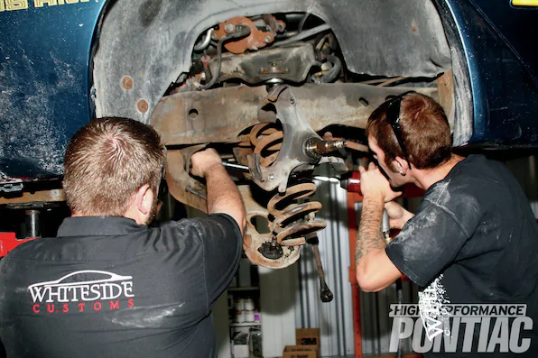
13. To provide enough clearance for the spring to be pulled out, a 21mm wrench and flex-head socket on an extension were used to loosen the bolts and twist the control arm enough for the spring to fall out.
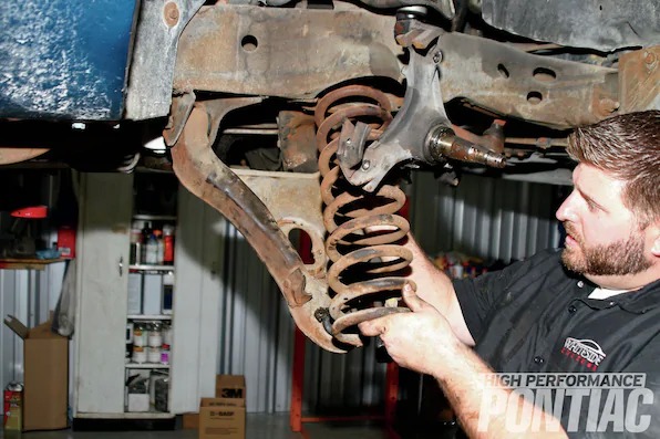
14. Mike inspects the spring and doesn’t find defects but understands now that the driver-side spring will require not only the removal of the steering shaft but the arduous job of loosening the lower control arms. Recently, PTFB came out with competition/race Daytona lower control arms that feature a rectangular-box design and can be fitted with either polyurethane or Delrin bushings (PN 2CS-130, retail $549).
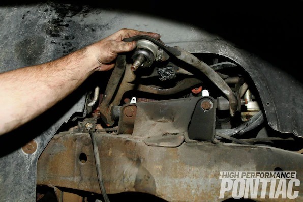
15. To finish removing the upper control arm, the spindle was removed along with the two upper-control-arm bolts. The control arm is lifted and a 13⁄16-inch socket and 3⁄4-inch wrench on the backside are used in combination to remove the remaining bolts.
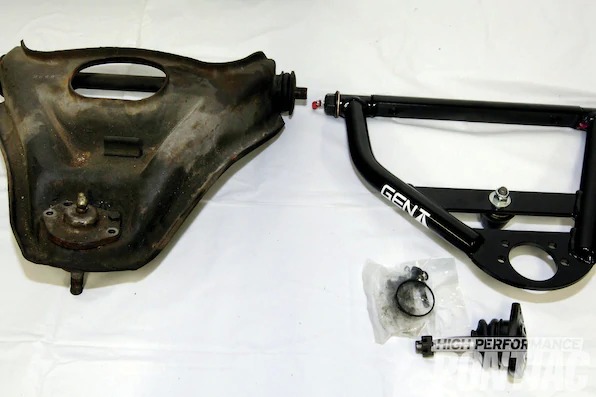
16. A comparison of the stock upper control arm on the left and Gen II Racing control arm on the right demonstrates the big differences between the two. Rather than a stamped piece, the Gen II units have interlocked welded tubes, billet offset cross shafts, solid pivot bushings (greaseable), and are both stronger and lighter. The revised ball-joint angle provides more wheel clearance, and the ability to add positive caster and increase the negative camber curve will allow a more sport oriented front-end alignment.
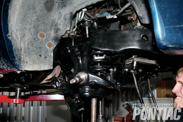
17. After installing the provided heavy-duty ball joint on the upper control arm, the front-end was thoroughly cleaned. The lower control arm was removed to be cleaned, and, along with the frame, was sprayed with a rust-converting black spray paint. New bushings were pressed into the lower control arms and new Moog ball joints and a bump stop round out the lower control arm restoration. After installing the lower control arm, the Gen II upper control arm is placed in position and both arms are torqued per the specifications. We did not install the upper-control-arm alignment shims. Instead we opted to let the front-end-alignment shop handle that task.
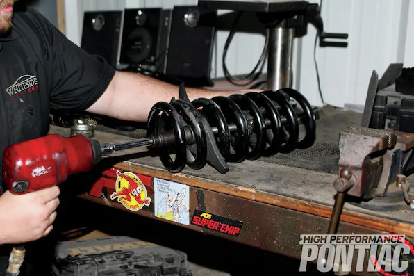
18. Before installing the replacement coilspring and replacing the shock absorber, the front springs need to be compressed in order to fit. Mike installed a coilspring compressor and used a 19mm socket and impact gun to compress the spring down to 13 inches (uncompressed was 15 inches).
19. He set up a pole jack under the lower control arm and made sure he had the two castle nuts (one for the lower-control-arm ball joint and a second for the upper control arm to spindle). Then he installed the spindle and put the castle nut on a few turns, installed a new spring isolator on the top of the spring, got the spring in position, and slowly raised the lower control arm until he could secure the castle nut on the top of the spindle. Afterwards, he removed the coilspring–compressor tool and tightened up the ball joints to specifications.
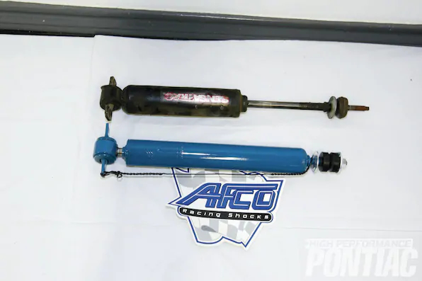
20. After consulting with PTFB, Randy opted for non-adjustable AFCO shocks (separately priced at $138 a pair). PTFB worked with AFCO to custom calibrate a set of front and rear stock-mount twin-tube shock absorbers. They feature firm calibration, and each shock is tailored to the overall ride-height adjustment so the piston stroke is centered to maintain consistent performance. A front Monroe and rear AFCO shock are displayed, top and bottom respectively.
21. The front shocks were mounted by sliding the shock body up through the hole in the lower control arm and into an access hole in the upper control arm. The top of each shock is retained with a polyurethane bushing, washer, and nut. The bottom was bolted on through the shock body with two bolts and torqued to spec.
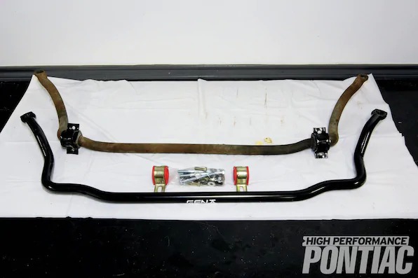
22. The Gen II front sway bar (bottom, PN OSC-500, $179) is titled a ’70-’81 1LE bar but is not a factory piece (1LE suspension packages were offered on certain years of Third- and Fourth-Generation Trans Ams and Formulas) but rather a replacement, solid sway bar with 10-percent greater stiffness. A nominal increase in dimensions (1.250 versus 1.200 for stock on top) plays a part, but the forged and machined ends are the real keys to less bar flex.
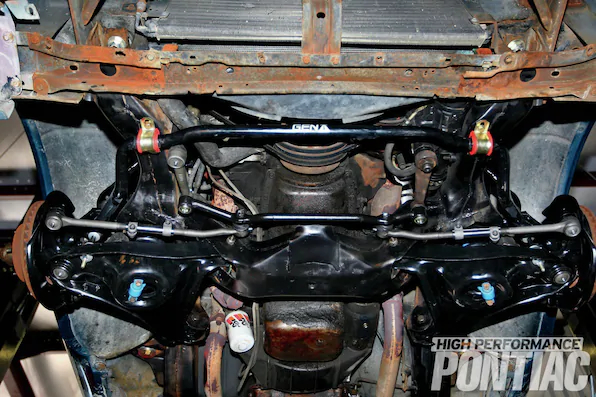
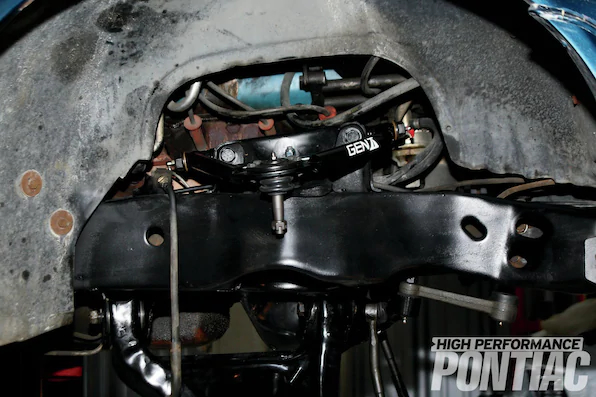
23. After the driver’s side was disassembled and then reassembled, the new Gen II sway bar was lifted up and bolted in. Note that the front sway bar is non-adjustable.
24. Moving to the rear, the wheels were removed and the rear leaf spring was inspected for damaged leafs. The rear leaf springs’ bushings on both ends are original and the rubber is cracked; leading to rear deflection on cornering and the tendency for axle wrap, which causes wheelhop on acceleration or deceleration.